In the last tutorial, we understood the data structure of IMU messages and how to visualize the data using a web application. In this tutorial, we will simulate IMU data for our vessel.
After completing this tutorial, you will be able to:
Subscribe to the odometry topic and publish IMU data
Calculate the orientation reported by the IMU
Calculate the angular velocity reported by the IMU
Calculate the linear acceleration reported by the IMU
Develop a node that simulates IMU data based on the vessel’s motion
18.1 Getting Started
We will be using the same repository as the previous tutorial. Once the previous tutorial deadline is over, your instructor will update the upstream repository with the necessary files for this tutorial and raise a pull request on your team repository. You will need to pull in the changes from the upstream repository to your team repository to start this tutorial. The instructions to pull in the changes are given in Appendix B.
After you complete the steps shown in Appendix B to synchronize your repository with the upstream repository, navigate to the root directory of your repository. Pull the latest changes made to your team repository onto your local machine.
cd <your-repository-name>
git pull origin main
The relevant folder structure of the repository for this tutorial is shown below.
All your group members can work independently on their own branches. However, you will have to merge your branches back to the main branch before the end of the tutorial. We learnt how to do this in Chapter 14 using pull requests.
First start docker desktop and then follow the instructions below to run the course docker container. Make sure to navigate in the terminal to the root folder of your repository.
For Windows:
./ros2_run_devdocker.bat
For Ubuntu (or MacOS):
./ros2_run_devdocker.sh
Source the ROS 2 environment by running the following command:
sros2
Notice that this is an alias for sourcing your ROS 2 workspace as well as the ROS 2 installation in the docker container. Remember that every time you perform a colcon build on your workspace, you need to source the ROS 2 environment again with the command above.
18.2 Create a new ROS2 package
Create a new ROS2 package inside /workspaces/mavlab/ros2_ws/src/student/tut_06
cd /workspaces/mavlab/ros2_ws/src/student/tut_06ros2 pkg create --build-type ament_python mav_imu_simulator --dependencies rclpy std_msgs nav_msgs sensor_msgs geometry_msgs --license MIT
18.3 Create a new node
Create a new node inside /workspaces/mavlab/ros2_ws/src/student/tut_06/mav_imu_simulator/mav_imu_simulator/
cd /workspaces/mavlab/ros2_ws/src/student/tut_06/mav_imu_simulator/mav_imu_simulatortouch mav_imu_simulator.py
Copy the following code into the mav_imu_simulator.py file:
Code
import rclpyfrom rclpy.node import Nodefrom nav_msgs.msg import Odometryfrom sensor_msgs.msg import Imuimport numpy as npimport syssys.path.append('/workspaces/mavlab/')from ros2_ws.src.student.tut_03.read_input import read_inputfrom ros2_ws.src.student.tut_03.class_vessel import Vesselfrom ros2_ws.src.student.tut_03.module_kinematics import eul_to_quat, eul_to_rotm, quat_to_eul, rotm_to_eulclass MavImuSimulator(Node):def__init__(self):super().__init__('mav_imu_simulator')# Read vessel parameters and create vessel instance vessel_params, hydrodynamic_data = read_input()self.vessel = Vessel(vessel_params, hydrodynamic_data)self.g = vessel_params['g']# Find IMU sensors and create publishersself.imu_sensors = []self.imu_publishers = []self.imu_timers = []self.vessel_state = np.zeros(13) count =0for sensor in vessel_params['sensors']:if sensor['sensor_type'] =='IMU': self.imu_sensors.append({'id': count,'position': np.array(sensor['sensor_location']),'orientation': np.array(sensor['sensor_orientation']),'topic': sensor['topic'],'rate': sensor['rate'],'orientation_covariance': np.array(sensor['noise'][0]['orientation_covariance']),'angular_velocity_covariance': np.array(sensor['noise'][2]['angular_velocity_covariance']),'linear_acceleration_covariance': np.array(sensor['noise'][1]['linear_acceleration_covariance']) })# Create publisher for this IMUself.imu_publishers.append(self.create_publisher(Imu, self.imu_sensors[count]['topic'], 10) )# Create timer for this IMUself.imu_timers.append(self.create_timer(1/self.imu_sensors[count]['rate'],lambda i=count: self.publish_imu_messages(i) ) ) count +=1# Subscribe to odometryself.subscription =self.create_subscription( Odometry,'/mav_odom',self.odom_callback,10 )def compute_imu_orientation(self, vessel_state, sensor_position, sensor_orientation, eul_flag=False ):""" Compute IMU orientation quaternion Args: vessel_state: 13x1 vessel state vector sensor_position: 3x1 sensor position vector sensor_orientation: 3x1 sensor orientation vector eul_flag: boolean flag to indicate if the orientation is in Euler angles Returns: quat_eul: 4x1 quaternion vector if eul_flag is False, otherwise 3x1 Euler angles """# Extract BCS orientation (assuming ZYX Euler angles) wrt GCS frame Theta_gb = vessel_state[9:12] # Sensor frame position and orientation with respect to BCS (assuming ZYX Euler angles) r_bs = sensor_position Theta_bs = sensor_orientation# Sensor frame orientation wrt GCS frame (assuming ZYX Euler angles) - Reported by sensor sensor_reported_orientation = np.zeros(3)#===========================================================================# TODO: Calculate orientation (in Euler angles) reported by sensor # in sensor frame#===========================================================================# Write your code herepass#===========================================================================ifnot eul_flag:# Convert orientation to quaternion quat_eul = eul_to_quat(sensor_reported_orientation)else: quat_eul = sensor_reported_orientationreturn quat_euldef compute_imu_angular_velocity(self, vessel_state, sensor_position, sensor_orientation ):""" Compute IMU angular velocity Args: vessel_state: 13x1 vessel state vector sensor_position: 3x1 sensor position vector sensor_orientation: 3x1 sensor orientation vector Returns: omega_s: 3x1 angular velocity vector in sensor frame """# Extract vessel angular velocity in body frame omega_b = vessel_state[3:6]# Sensor position and orientation with respect to BCS r_bs = sensor_position Theta_bs = sensor_orientation# Compute angular velocity in sensor frame omega_s = np.zeros(3)#===========================================================================# TODO: Calculate angular velocity in sensor frame#===========================================================================# Write your code herepass#===========================================================================return omega_sdef compute_imu_linear_acceleration(self, vessel_state, sensor_position, sensor_orientation ):""" Compute IMU linear acceleration including centripetal effects Args: vessel_state: 13x1 vessel state vector sensor_position: 3x1 sensor position vector sensor_orientation: 3x1 sensor orientation vector Returns: a_s: 3x1 linear acceleration vector in sensor frame """# Extract vessel linear and angular velocities v = vessel_state[0:3] omega = vessel_state[3:6] eul = vessel_state[9:12]# Sensor position and orientation with respect to BCS r_bs = sensor_position Theta_bs = sensor_orientation imu_eul =self.compute_imu_orientation(vessel_state, sensor_position, sensor_orientation, eul_flag=True) a_s = np.zeros(3)#===========================================================================# TODO: Calculate linear acceleration in sensor frame#===========================================================================# Write your code herepass#===========================================================================# Add gravity component to the linear acceleration gravity = np.array([0, 0, -self.g]) gravity_s = eul_to_rotm(imu_eul).T @ gravity a_s = a_s + gravity_sreturn a_sdef odom_callback(self, msg):"""Handle incoming odometry messages"""# Extract state from odometry messageself.vessel_state = np.zeros(13)self.vessel_state[0:3] = [msg.twist.twist.linear.x, msg.twist.twist.linear.y, msg.twist.twist.linear.z]self.vessel_state[3:6] = [msg.twist.twist.angular.x, msg.twist.twist.angular.y, msg.twist.twist.angular.z]self.vessel_state[6:9] = [msg.pose.pose.position.x, msg.pose.pose.position.y, msg.pose.pose.position.z]# Extract Euler angles from quaternionself.vessel_state[9:12] = quat_to_eul([msg.pose.pose.orientation.w, msg.pose.pose.orientation.x, msg.pose.pose.orientation.y, msg.pose.pose.orientation.z])def publish_imu_messages(self, i):"""Publish IMU messages""" sensor =self.imu_sensors[i]# Update each IMU imu_msg = Imu() imu_msg.header.stamp =self.get_clock().now().to_msg() imu_msg.header.frame_id =f'imu_{i:02d}'# Compute IMU measurements orientation =self.compute_imu_orientation(self.vessel_state, sensor['position'], sensor['orientation']) angular_velocity =self.compute_imu_angular_velocity(self.vessel_state, sensor['position'], sensor['orientation']) linear_acceleration =self.compute_imu_linear_acceleration(self.vessel_state, sensor['position'], sensor['orientation'])# Populate IMU message imu_msg.orientation.w = orientation[0] imu_msg.orientation.x = orientation[1] imu_msg.orientation.y = orientation[2] imu_msg.orientation.z = orientation[3] imu_msg.angular_velocity.x = angular_velocity[0] imu_msg.angular_velocity.y = angular_velocity[1] imu_msg.angular_velocity.z = angular_velocity[2] imu_msg.linear_acceleration.x = linear_acceleration[0] imu_msg.linear_acceleration.y = linear_acceleration[1] imu_msg.linear_acceleration.z = linear_acceleration[2]# Set covariances from input file imu_msg.orientation_covariance = sensor['orientation_covariance'].flatten() imu_msg.angular_velocity_covariance = sensor['angular_velocity_covariance'].flatten() imu_msg.linear_acceleration_covariance = sensor['linear_acceleration_covariance'].flatten()# Publish IMU messageself.imu_publishers[i].publish(imu_msg)def main(args=None): rclpy.init(args=args) node = MavImuSimulator() rclpy.spin(node) node.destroy_node() rclpy.shutdown()if__name__=='__main__': main()
Let’s break down the code in the mav_imu_simulator.py file. This node subscribes to the odometry data from the vessel simulator and publishes the IMU data to the /imu/data topic. The odometry data provides the position, orientation, linear velocity and angular velocity of the vessel. The position and orientation of the IMU sensor need not necessarily coincide with the origin of the BCS. Similarly the sensor also need not be oriented with its frame of reference parallel to the BCS. Therefore, the measurements of the IMU need to be computed based on the position and orientation of the IMU sensor with respect to the BCS.
If you observe, the input file (originally created in Chapter 15) located in tut_03 folder has been modified in this tutorial to include the IMU sensor parameters. The sensors list in the input file now contains the parameters for the different sensors that the vessel is equipped with. In this tutorial we are only interested in the IMU sensor. The sensors list in the input file now contains the following additional lines:
These lines describe the sensor parameters for the IMU and the UWB sensor.
18.3.1 Implementation Tasks
There are three tasks to complete in this tutorial. In each of these tasks, the vessel state vector is assumed to be \(13 \times 1\) vector as defined in Chapter 15. The first three elements denote the components of the linear velocity of the vessel in the BCS. The next three elements denote the components of the angular velocity of the vessel in the BCS. The next three elements denote the position of the vessel in the GCS. The next three elements denote the Euler angles of the vessel in the GCS. The last element denotes the actual rudder angle.
In addition to the state vector, the functions also take the sensor position and orientation as input. The sensor position is a \(3 \times 1\) vector denoting the position of the sensor in the BCS. The sensor orientation is a \(3 \times 1\) vector denoting the orientation of the sensor with respect to BCS.
Task 1: Complete the compute_imu_orientation function
Location:mav_imu_simulator.py, compute_imu_orientation() function
Description: The compute_imu_orientation function computes the orientation that the IMU sensor reports.
Input:
vessel_state: 13x1 vessel state vector
sensor_position: 3x1 sensor position vector
sensor_orientation: 3x1 sensor orientation vector
eul_flag: boolean flag to indicate if the orientation is to be returned in Euler angles or quaternion form
Output:
quat_eul: 4x1 quaternion vector if eul_flag is False, otherwise 3x1 Euler angles
The code to convert the Euler angles to quaternion is already programmed for you. You only need to compute the euler angles that will be reported by the IMU sensor.
Hint: The orientation reported by the IMU will be composition of the rotations from the GCS to the BCS and from the BCS to the sensor frame.
Task 2: Complete the compute_imu_angular_velocity function
Location:mav_imu_simulator.py, compute_imu_angular_velocity() function
Description: The compute_imu_angular_velocity function computes the angular velocity that the IMU sensor reports.
Input:
vessel_state: 13x1 vessel state vector
sensor_position: 3x1 sensor position vector
sensor_orientation: 3x1 sensor orientation vector
Output:
omega_s: 3x1 angular velocity vector in sensor frame
Hint: Angular velocity vector itself does not change when expressed in different frames of reference. The angular velocity in the sensor frame is the same vector as the angular velocity of the vessel in the BCS. However, the sensor frame need not be aligned with the BCS and this will result in different components of the angular velocity vector in the sensor frame as compared to the BCS.
Task 3: Complete the compute_imu_linear_acceleration function
Location:mav_imu_simulator.py, compute_imu_linear_acceleration() function
Description: The compute_imu_linear_acceleration function computes the linear acceleration that the IMU sensor reports.
Input:
vessel_state: 13x1 vessel state vector
sensor_position: 3x1 sensor position vector
sensor_orientation: 3x1 sensor orientation vector
Output:
a_s: 3x1 linear acceleration vector in sensor frame
The acceleration due to gravity is given by \(g = 9.80665\) m/s\(^2\).
Hint: The computation of the linear acceleration in the sensor frame is NOT trivial. You need to derive the expression in terms of the vessel state vector and the sensor position and orientation. Remember that acceleration is the rate of change of velocity only in an inertial frame of reference! The ODE defining the dynamics of your vessel only provides the derivative of the linear and angular velocities and not linear and angular accelerations.
18.4 Create a launch file
Create a launch file inside /workspaces/mavlab/ros2_ws/src/student/tut_06/mav_imu_simulator/mav_imu_simulator/launch
cd /workspaces/mavlab/ros2_ws/src/student/tut_06/mav_imu_simulator/mkdir launchcd launchtouch mav_imu_simulator_launch.py
Copy the following code into the mav_imu_simulator_launch.py file:
Code
from launch import LaunchDescriptionfrom launch_ros.actions import Nodefrom launch.actions import ExecuteProcessfrom launch.substitutions import PathJoinSubstitutionfrom launch_ros.substitutions import FindPackageSharefrom launch.actions import IncludeLaunchDescriptionfrom launch.launch_description_sources import AnyLaunchDescriptionSourcedef generate_launch_description():# Path to the rosbridge launch file rosbridge_launch = PathJoinSubstitution([ FindPackageShare('rosbridge_server'),'launch','rosbridge_websocket_launch.xml' ])# Path to the built web directory web_build_dir = PathJoinSubstitution([ FindPackageShare('mav_imu_visualizer'),'web' ])return LaunchDescription([# Start the HTTP server to serve web files ExecuteProcess( cmd=['python3', '-m', 'http.server', '8000', '--directory', web_build_dir], name='http_server', output='screen' ), Node( package='mav_simulator', executable='mav_simulate', name='mav_simulate', output='screen' ), Node( package='mav_simulator', executable='mav_control', name='mav_control', output='screen' ), Node( package='mav_imu_simulator', executable='mav_imu_simulator', name='mav_imu_simulator', output='screen' ), IncludeLaunchDescription( AnyLaunchDescriptionSource(rosbridge_launch) ) ])
Let’s break down the code in the launch file. This launch file is similar to the launch file in the previous tutorial. However, in this launch file, we are starting the mav_simulate and mav_control nodes using the package we built in Chapter 16. This will start the vessel simulator and the controller. The simulator will publish the odometry data to the /mav_odom topic. The controller will subscribe to the odometry data and publish the control commands to the /mav_rudder_command topic. In addition to this, the launch file also starts a ROS bridge server and a HTTP server to serve the web files for the web application developed in Chapter 17. The ROS bridge server will be used to communicate the data being published on the topic /imu/data to the web application. Finally, the launch file starts the mav_imu_simulator node which will subscribe to the odometry data from the simulator and publish the IMU data to the /imu/data topic. Unlike in the last tutorial where we visualized the IMU data from a ros bag file, in this tutorial we will visualize the IMU data from the IMU simulator we develop in this tutorial.
In order for the launch file to work, we need to make sure that the setup.py file for the mav_imu_simulator package is updated. Navigate to the setup.py file:
cd /workspaces/mavlab/ros2_ws/src/student/tut_06/mav_imu_simulator
Overwrite the setup.py file with the following code:
You should see an output similar to the following:
[INFO] [launch]: All log files can be found below /home/mavlab/.ros/log/2025-02-22-11-57-32-677973-iit-m-490
[INFO] [launch]: Default logging verbosity is set to INFO
[INFO] [http_server-1]: process started with pid [491]
[INFO] [mav_simulate-2]: process started with pid [493]
[INFO] [mav_control-3]: process started with pid [495]
[INFO] [mav_imu_simulator-4]: process started with pid [497]
[INFO] [rosbridge_websocket-5]: process started with pid [499]
[INFO] [rosapi_node-6]: process started with pid [501]
[rosbridge_websocket-5] [INFO] [1740225453.504476880] [rosbridge_websocket]: Rosbridge WebSocket server started on port 9090
[mav_control-3] [INFO] [1740225453.509661554] [mav_control]: MAV Controller initialized
[mav_control-3] [INFO] [1740225453.762915500] [mav_control]:
[mav_control-3] Time: 0.28s
[mav_control-3] Rudder Command: 5.00 deg
[mav_control-3]
[mav_simulate-2] [INFO] [1740225453.798229386] [mav_simulate]:
[mav_simulate-2] Time: 0.10s
[mav_simulate-2] Position (x,y,z): [0.05, 0.00, 0.00]
[mav_simulate-2] Euler angles (phi,theta,psi): [0.00, 0.00, 0.00]
[mav_simulate-2] Velocity (u,v,w): [0.50, 0.00, 0.00]
[mav_simulate-2] Angular velocity (p,q,r): [0.00, 0.00, 0.00]
[mav_simulate-2] Rudder Command: 0.00 deg
[mav_simulate-2]
[mav_simulate-2] [INFO] [1740225453.861802078] [mav_simulate]:
[mav_simulate-2] Time: 0.20s
[mav_simulate-2] Position (x,y,z): [0.10, 0.00, 0.00]
[mav_simulate-2] Euler angles (phi,theta,psi): [0.00, 0.00, -0.01]
[mav_simulate-2] Velocity (u,v,w): [0.50, 0.00, 0.00]
[mav_simulate-2] Angular velocity (p,q,r): [0.00, 0.00, -0.00]
[mav_simulate-2] Rudder Command: 3.16 deg
[mav_simulate-2]
[mav_control-3] [INFO] [1740225453.862796753] [mav_control]:
[mav_control-3] Time: 0.37s
[mav_control-3] Rudder Command: 5.00 deg
You can access the web application by opening the following URL in your web browser:
http://localhost:8000/
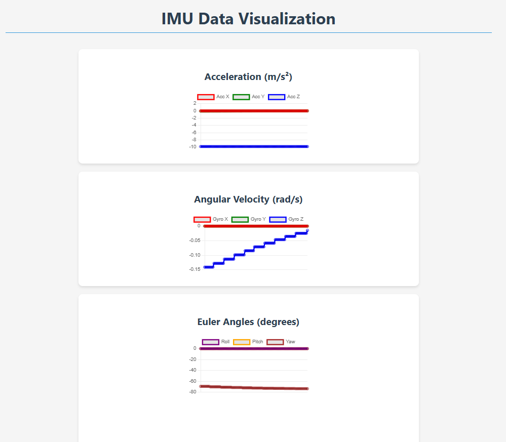
You should see a plot of the IMU data as shown in Figure 18.1.
Figure 18.1: IMU simulator
Since the switching rudder command is applied, you should see the turn rate \(r\) of the vessel switch between \(-0.15\) rad/s and \(0.15\) rad/s. When the turn rate is positive the yaw angle \(\psi\) should increase and when the turn rate is negative the yaw angle should decrease. You should also see that acceleration in the \(z\) is close to the acceleration due to gravity.
18.7 Evaluation
The evaluation of the tutorial will be performed in the classroom. Notice that this is a group activity. You will be working in a group of 4 students. The evaluation will be performed on the group level. In order to pass the tutorial, the group must pass all the tests in the GitHub Actions workflow and also be able to answer all the questions during the evaluation in the classroom. Those who are not present in the classroom on the day of evaluation will not be able to participate in the evaluation and will automatically fail the tutorial.
While one of the objectives of these tutorials is to give you hands on experience with coding and practical implementation, the more important goal is to help you relate what you are doing in your tutorials to the underlying concepts discussed in the class. Therefore, while you are working on the implementation tasks, make sure you are also thinking about the underlying concepts and how they are being applied in the code.
Some questions to think about while you are working on the implementation tasks:
What is the difference between the orientation reported by the IMU and the orientation of the vessel in the vessel state vector? How do we derive the former from the latter?
What is the difference between the angular velocity reported by the IMU and the angular velocity of the vessel in the vessel state vector? How do we derive the former from the latter?
What is the difference between the linear acceleration reported by the IMU and the linear acceleration of the vessel? How do we derive the former from the latter?
How do we caluclate the acceleration of the vessel in the BCS?
Why did we add the acceleration due to gravity to the linear acceleration reported by the IMU?
How do you think we obtained the covariance values for the IMU measurements?
Are we adding noise to our measurements?
18.8 Instructor Feedback through Pull Requests
Commit your changes to the remote repository often. This will help you to track your progress and also help you to revert to a working version if you make a mistake. In addition, the instructor and TA will be able to provide you with feedback on your code through the Feedback pull request available in your repository. Please do not close this pull request.