6 Turning Circle Maneuver
The turning circle maneuver is one of the fundamental ship maneuvers and is used to calculate the steady turning radius of the vessel. The vessel is first allowed to achieve the design speed \(U\). Once the vessel is moving at a steady speed in a straight line, a hard rudder of usually \(35^\circ\) is applied. Upon application of the rudder, the vessel goes through three phases of turning as shown in Figure 6.1
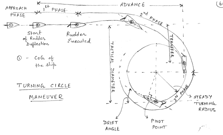
6.1 First Phase of the Turning Circle Maneuver
In the first phase, the vessel undergoes a transient motion and begins to pivot. The vessel experiences accelerations in surge, sway and yaw modes. Therefore, this phase is also kwown as acceleration phase. Once the rudder has been executed, sway force \(Y = Y_{\delta} \delta\) and yaw moment \(N = N_{\delta}\delta\) act on the vessel. However, the large mass and inertia of the vessel prevent the sway velocity \(v\) and yaw velocity \(r\) from increasing instantaneously.
In the first phase, it can be assumed that \(v \approx r \approx 0\). Thus the steering equations reduce as shown in \(\eqref{eq-sway-linear-eom-phase-1}\) and \(\eqref{eq-yaw-linear-eom-phase-1}\).
\[\begin{align} (m - Y_{\dot{v}}) \dot{v} - (Y_{\dot{r}} - m x_G) \dot{r} - Y_v \cancelto{0}{v} - (Y_r - mU) \cancelto{0}{r} = Y_{\delta} \delta \label{eq-sway-linear-eom-phase-1} \end{align}\]
\[\begin{align} (I_z - N_{\dot{r}}) \dot{r} - (N_{\dot{v}} - m x_G) \dot{v} - N_v \cancelto{0}{v} - (N_r - mx_GU) \cancelto{0}{r} = N_{\delta} \delta \label{eq-yaw-linear-eom-phase-1} \end{align}\]
In the matrix form, the equations can be expressed as
\[\begin{align} \begin{bmatrix} (m - Y_{\dot{v}}) & - (Y_{\dot{r}} - m x_G) \\ - (N_{\dot{v}} - m x_G) & (I_z - N_{\dot{r}}) \\ \end{bmatrix} \begin{bmatrix} \dot{v} \\ \dot{r} \end{bmatrix} = \begin{bmatrix} Y_{\delta} \\ N_{\delta} \end{bmatrix} \delta \end{align}\]
Solving this matrix system of equation yields
\[\begin{align} \dot{v} = \frac{(I_z - N_{\dot{r}}) Y_{\delta} + (Y_{\dot{r}} - m x_G) N_{\delta}}{(m - Y_{\dot{v}})(I_z - N_{\dot{r}}) - (N_{\dot{v}} - m x_G)(Y_{\dot{r}} - m x_G)} \delta \end{align}\]
\[\begin{align} \dot{r} = \frac{(m - Y_{\dot{v}})N_{\delta} + (N_{\dot{v}} - m x_G)Y_{\delta}}{(m - Y_{\dot{v}})(I_z - N_{\dot{r}}) - (N_{\dot{v}} - m x_G)(Y_{\dot{r}} - m x_G)} \delta \end{align}\]
Neglecting the cross-coupling terms that are generally smaller than the diagonal terms yields
\[\begin{align} \dot{v} = \frac{Y_{\delta} \delta}{m - Y_{\dot{v}}} \end{align}\]
\[\begin{align} \dot{r} = \frac{N_{\delta} \delta}{I_z - N_{\dot{r}}} \end{align}\]
For \(\delta > 0\) defined in the clockwise direction as shown in Figure 6.2. Note that \(Y_{\delta} > 0\) so that \(\delta > 0\) will result in positive sway rudder force. This force will cause a moment about the BCS origin in the direction shown in Figure 6.2 and the ship will eventually turn towards the port side. As this yaw moment due to the rudder is opposite to the positive convention of yaw moment about BCS, this implies that \(N_{\delta} < 0\).
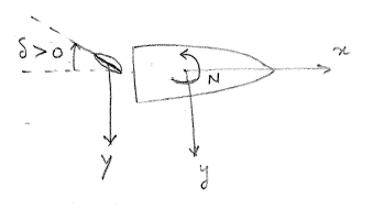
For \(\delta < 0\), the vessel will turn towards starboard. For a starboard turn, \(\dot{v} = \frac{Y_{\delta} \delta}{m - Y_{\dot{v}}} < 0\). Thus the ship will accelerate towards the port side during the first phase of the turn. Similarly, \(\dot{r} = \frac{N_{\delta} \delta}{I_z - N_{\dot{r}}} > 0\) for \(\delta < 0\) and hence the ship will experience clockwise rotational acceleration. Thus in the first phase of the turn, the vessel will assume an angle of attack to its path and this will eventually turn the ship in the next phases.
6.2 Second Phase of the Turning Circle Maneuver
The first phase of the turn is very short as the accelerations give rise to sway velocity \(v\) and yaw velocity \(r\) and the vessel enters the second phase of the turn. During this phase, \(\dot{v} \neq 0\), \(\dot{r} \neq 0\), \(v \neq 0\), \(r \neq 0\). The speed of the vessel also reduces from the design speed and hence \(u < U\).
For a starboard turn, \(\dot{v} < 0\) and \(\dot{r} > 0\). In the second phase, the vessel develops a positive drift (drift angle \(\beta\) is defined in the positive orientation from the velocity vector to the longitudinal direction of the vessel) leading to a positive sway force \(Y_v v\). This overcomes the rudder force \(Y_{\delta} \delta\) (acting in the opposite direction to the sway force) and eventually \(\dot{v} \rightarrow 0\). Typically \(\dot{r} \rightarrow 0\) by the end of second phase. The variation of the velocities and accelerations over the different phases of the turn are shown in Figure 6.3. Note that to accommodate all the plots concisely, the plot shows \(-\delta\), \(-v\) and \(-\dot{v}\) along the positive y-axis.
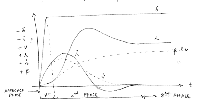
Unlike the first phase, the analysis of second phase of turn cannot be simplified. The linear assumption too does not hold well in this phase and the nonlinear equations of motion need to be integrated to analyze this phase of the turn. These nonlinear equations of motion will be described in detail in next chapter.
6.3 Third Phase of the Turning Circle Maneuver
By the end of the second phase, equilibrium is reached between the rudder forces and the hull forces and the vessel settles into a steady turn with constant radius \(R\). This steady phase is the third phase of the turn where \(\dot{v} = \dot{r} = 0\) but \(v \neq 0\) and \(r \neq 0\). Thus the linearized equations of motion can be reduced as shown in \(\eqref{eq-sway-linear-eom-phase-3}\) and \(\eqref{eq-yaw-linear-eom-phase-3}\).
\[\begin{align} (m - Y_{\dot{v}}) \cancelto{0}{\dot{v}} - (Y_{\dot{r}} - m x_G) \cancelto{0}{\dot{r}} - Y_v v - (Y_r - mU) r = Y_{\delta} \delta \label{eq-sway-linear-eom-phase-3} \end{align}\]
\[\begin{align} (I_z - N_{\dot{r}}) \cancelto{0}{\dot{r}} - (N_{\dot{v}} - m x_G) \cancelto{0}{\dot{v}} - N_v v - (N_r - mx_GU) r = N_{\delta} \delta \label{eq-yaw-linear-eom-phase-3} \end{align}\]
Expressing them in the matrix form results in
\[\begin{align} \begin{bmatrix} - Y_v & - (Y_r - mU) \\ - N_v & - (N_r - mx_GU) \end{bmatrix} \begin{bmatrix} v \\ r \end{bmatrix} = \begin{bmatrix} Y_{\delta} \\ N_{\delta} \end{bmatrix} \delta \end{align}\]
Solving this matrix system of equation yields
\[\begin{align} v = -\frac{(N_r - mx_GU) Y_{\delta} - (Y_r - mU) N_{\delta}}{Y_v (N_r - mx_GU) - N_v (Y_r - mU)} \delta \label{eq-v-phase-3} \end{align}\]
\[\begin{align} r = - \frac{Y_v N_{\delta} - N_v Y_{\delta}}{Y_v (N_r - mx_GU) - N_v (Y_r - mU)} \delta \label{eq-r-phase-3} \end{align}\]
It can be seen that from \(\eqref{eq-v-phase-3}\) and \(\eqref{eq-r-phase-3}\) that the magnitudes of \(v\) and \(r\) are proportional to the rudder angle \(\delta\). For a starboard turn \(\delta <0\), \(v < 0\) and \(r>0\) in the steady state.
When assuming linearized equations of motion, there is no loss of speed during the turn. It is a limitation of the linear theory. To capture the effect of speed loss, the nonlinear equations of motion (described in the next chapter) must be used. The drift angle \(\beta\) under the assumptions of linear theory is given by
\[\begin{align} \tan(\beta) = -\frac{v}{u} \approx \beta \end{align}\]
It can be seen that the drift angle \(\beta \propto \delta\). Thus, an increase in rudder results in a larger drift angle and a sharper turn. The radius of the turn is steady state is given by \(R = U/r\) and is inversely proportional to the rudder angle \(\delta\).
6.4 Pivot Point
During a turn, for an observer onboard the ship, the vessel appears to pivot about the pivot point. Based on empirical data, the pivot point lies somewhere between the bow and \(0.2L\) aft of the bow. It is notionally the point where the angle of attack of the fluid is zero. The pivot point location from BCS origin is denoted as \(x_c\) and satisfies the relation shown in \(\eqref{eq-pivot-1}\).
\[\begin{align} v + r x_c = 0 \implies x_c = \frac{-v}{r} = \frac{-v}{U} \frac{U}{r} = R\sin(\beta) \approx R\beta \label{eq-pivot-1} \end{align}\]
For different turns, the pivot point remains (approximately) at a constant location. Larger values of \(R\) are associated with smaller values of \(\beta\) and vice versa to keep the product \(R\beta\) relatively constant.
6.5 Steady Radius of Turn
The non-dimensional radius of turn is given by
\[\begin{align} R' = \frac{1}{r'} = - \frac{1}{\delta} \frac{C'}{Y_v'N_{\delta}' - N_v'Y_{\delta}'} \end{align}\]
where \(C'=Y_v' (N_r' - m'x_G') - N_v' (Y_r' - m')\) is the non-dimensional stability index introduced in Chapter 4. From the magnitude and sign assessment of hydrodynamic derivatives discussed in Chapter 4, \(Y_v'N_{\delta}' - N_v'Y_{\delta}' > 0\). Thus for a stable ship \((C'>0)\), a negative rudder \(\delta < 0\) will result in a starboard turn and a positive value of \(R'\). \(R'\) increases with \(C'\). A more stable vessel is sluggish to turn.
For an unstable ship, \(\delta<0\) results in a negative \(R\) (meaning that the vessel will turn towards port). Thus the above discussed analysis is not valid for unstable ship. The linearization is not valid and nonlinear analysis is required for such cases.
6.6 Heel Angle in a Turn
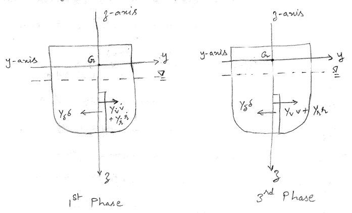
Although the rudder is used to control the motions in horizontal plane, due to the coupling effects in the equations of motion (see Chapter 2) motions are induced in the vertical modes too. Particularly, roll motion during a turn can be of particular significance for many ships.
Consider a vessel turning to the starboard due to a starboard rudder \(\delta < 0\). During the first phase of the turn, the equilibrium of lateral forces is given by
\[\begin{align} Y_{\delta} \delta + (Y_{\dot{v}} - m) \dot{v} + (Y_{\dot{r}} - m x_G ) \dot{r} = 0 \label{eq-sway-equilibrium-turning} \end{align}\]
Each of the forces in \(\eqref{eq-sway-equilibrium-turning}\) are graphically depicted in Figure 6.4. It can be seen that all these forces do not act at the same point. The rudder force \(Y_{\delta} \delta\) acts at a point within the span of the rudder. The hull hydrodynamic force \(Y_{\dot{v}} \dot{v} + Y_{\dot{r}} \dot{r}\) acts at a representative point within the draft of the vessel. The inertia forces act at the center of gravity \(G\) (which can be above the waterline too). These forces will result in a non-zero moment about an axis parallel to the x-axis of BCS and passing through the center of gravity and thus result in the vessel experiencing a heel during the first phase of the turn.
The forces acting on the vessel during the first phase of a starboard turn are:
- \(Y_{\delta} \delta < 0\) and relatively large in magnitude as \(\delta < 0\) for starboard turn and \(Y_{\delta} > 0\)
- \(Y_{\dot{v}} \dot{v} > 0\) and relatively large in magnitude as \(\dot{v} < 0\) for a starboard turn and \(Y_{\dot{v}} < 0\)
- \(Y_{\dot{r}} \dot{r}\) is small in magnitude and of uncertain sign
- \(-m\dot{v} > 0\) and large in magnitude
- \(-m x_G \dot{r}\) is small in magnitude
The primary competing forces for sway equilibrium are \(Y_{\delta}\delta < 0\) and \((Y_{\dot{v}} - m) \dot{v} > 0\). Since the point of action of \(Y_{\delta}\delta\) is lower than \(Y_{\dot{v}} \dot{v} + Y_{\dot{r}} \dot{r}\) , the vessel will heel inwards into the turn (towards starboard for a starboard turn).
During the third phase of the turn, the equilibrium of lateral forces is given by
\[\begin{align} Y_{\delta} \delta + Y_v v + (Y_r - m U) r = 0 \end{align}\]
The forces acting on the vessel during the third phase of a starboard turn are:
- \(Y_{\delta} \delta < 0\) as \(\delta < 0\) for starboard turn and \(Y_{\delta} > 0\)
- \(Y_{v} v > 0\) and large in magnitude as \(v < 0\) for a starboard turn and \(Y_{v} < 0\)
- \(Y_{r} r\) is small in magnitude and of uncertain sign
- \(-mUr < 0\) is large in magnitude
In the third phase of the turn, the rudder hydrodynamic force \(Y_{\delta} \delta\) is much smaller in magnitude in comparison to the hydrodynamic forces generated due to the hull \((Y_v v + Y_r r) > 0\). The hydrodynamic forces are balanced by the inertial forces \(-mUr < 0\) to maintain the turn. The moment about the center of gravity due to hull hydrodynamic forces are much larger in magnitude than the moment generated by the rudder forces even though the rudder forces act with a larger lever arm. Therefore, in the third phase of the turn, the vessel will heel outwards (towards the port side for a starboard turn).
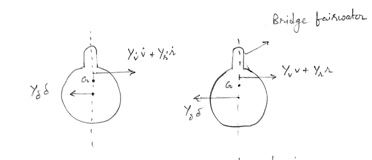
Consider underwater vehicles such as submarines that have a bridge fairwater. The bridge fairwater contributes significantly to the magnitude of \(Y_{\dot{v}} \dot{v}\) in the first phase of the turn and to \(Y_v v\) in the third phase of the turn. The point of action of the hydrodynamic force on the hull shifts up significantly due to the bridge fairwater. If this shift is sufficiently high, it can be seen that for a starboard turn, the submarine will heel inwards during the third phase of the turn and outwards during the first phase of the turn.
6.7 Exercises
A ship with length \(150\) m and design speed \(U = 15\) m/s has non-dimensional mass \(m' = 0.2\) and \(Y'_{\dot{v}} = -0.15\). Calculate the non-dimensional sway acceleration \(\dot{v}'\) if the non-dimensional rudder force \(Y'_{\delta}\delta = 0.02\) is applied during the first phase of turning.
For a ship in a first phase of a turn with non-dimensional derivatives \(Y'_{\delta} = 0.15\) and \(N'_{\delta} = -0.08\), determine the signs of sway acceleration \(\dot{v}'\) and yaw acceleration \(\dot{r}'\) for a port turn with \(\delta = 15^{\circ}\).
A vessel with a length \(L = 100\) m and design speed \(U = 8\) m/s has a steady non-dimensional turning radius \(R' = 3.5\). Calculate the yaw rate \(r\) during the steady turn.
During the steady phase of a turn, a ship has non-dimensional velocities \(v' = -0.31\) and \(u' = 0.95\). Calculate the drift angle \(\beta\).
A ship has the following non-dimensional parameters: \(Y'_v = -0.3\), \(Y'_r = -0.12\), \(N'_v = -0.15\), \(N'_r = -0.04\), \(Y'_{\delta} = 0.12\) and \(N'_{\delta} = -0.05\). If \(m' = 0.25\) and \(x'_G = 0.02\), set up the matrix equation for the steady-state turn where the rudder angle is \(\delta = 20^{{\circ}}\).
For a ship with non-dimensional pivot point location \(x'_c = 0.35\) (measured from midship) and drift angle \(\beta = 8^{\circ}\), calculate the non-dimensional turning radius \(R'\).
A vessel of length \(L = 160\) m and design speed \(U = 9\) m/s has non-dimensional rudder derivative \(Y'_{\delta} = 0.12\) and applies a rudder angle of \(30°\). If \((m' - Y'_{\dot{v}}) = 0.35\), calculate the approximate initial sway acceleration.
During a steady turn, a ship has non-dimensional yaw rate \(r' = 0.3\) and \(u' = 0.9\). Calculate the location of the pivot point in the BCS frame of reference if the length of the vessel is \(L = 120\) m.
A ship of length \(L=145\) m has a stability index \(C' = 0.25\) and \(Y'_v N'_{\delta} - N'_v Y'_{\delta} = 0.18\). Calculate the steady-state turning radius \(R\) for \(\delta = 25^{\circ}\).
For a ship of length \(L=150\) m and design speed \(U=10\) m/s, with non-dimensional vertical force application points \(z'_{rudder} = 0.04\) and \(z'_{hull} = 0.06\) relative to the keel, calculate the the roll moment (in MNm)experienced by the ship in the first phase of the turn if both non-dimensional horizontal forces have the same magnitude \(|F'_{rudder}| = |F'_{hull}| = 0.15\) but act in opposite directions. The non-dimensional center of gravity is at \(z'_G = 0.07\). Assume density of seawater \(\rho = 1025\) kg/m\(^3\).
A ship has the following non-dimensional parameters:
- \(Y'_v = -0.35\), \(Y'_r = -0.15\), \(N'_v = -0.18\), \(N'_r = -0.50\)
- \(Y'_{\delta} = 0.14\), \(N'_{\delta} = -0.06\)
- \(m' = 0.28\), \(x'_G = 0.025\)
Calculate the steady-state non-dimensional velocities \(v'\) and \(r'\) for \(\delta = 35^{{\circ}}\). Also determine the non-dimensional turning radius \(R'\) and drift angle \(\beta\).
A vessel has non-dimensional stability index \(C' = 0.32\) and is conducting turns at three different rudder angles: \(15^{{\circ}}\), \(25^{{\circ}}\), and \(35^{{\circ}}\). If \(Y'_v N'_{\delta} - N'_v Y'_{\delta} = 0.022\):
- Calculate \(R'\) for each rudder angle
- Determine if the relationship between \(R'\) and \(\delta\) is linear
- Find the percentage change in \(R'\) when increasing \(\delta\) from \(15^{{\circ}}\) to \(25^{{\circ}}\) and from \(25^{{\circ}}\) to \(35^{{\circ}}\)
For a ship with non-dimensional parameters \(m' = 0.3\), \(I'_z = 0.062\), \(Y'_{\dot{v}} = -0.2\), \(N'_{\dot{r}} = -0.05\), \(Y'_{\dot{r}} = -0.015\), \(N'_{\dot{v}} = -0.01\), \(Y'_{\delta} = 0.12\), \(N'_{\delta} = -0.05\), and \(x'_G = 0.03\):
- Set up and solve the complete first-phase acceleration equations for \(\delta = 15^{{\circ}}\)
- Calculate the percentage error in sway and yaw accelerations if cross-coupling terms are neglected
A ship has non-dimensional pivot point location \(x'_c = 0.32\) during a steady turn. Using the relationships between \(R'\), \(\beta\), and \(x'_c\):
- Calculate \(R'\) if \(\beta = 5^{{\circ}}\)
- If the rudder angle is doubled, determine the new values of \(R'\), \(\beta\), and \(x'_c\)
Answer Key
The sway acceleration is \(0.09\) m/s\(^2\)
As \(\delta = 15^{\circ}\) is a port turn, \(\dot{v}' > 0\) and \(\dot{r}' < 0\)
The yaw rate is \(r = 0.02\) rad/s
The drift angle is \(\beta = 18.07^{\circ}\)
The non-dimensional matrix equation for the steady-state turn is
\[\begin{align*} \begin{bmatrix} -Y_v' & - (Y_r' - m'x_G') \\ -N_v' & - (N_r' - m'x_G') \end{bmatrix} \begin{bmatrix} v' \\ r' \end{bmatrix} = \begin{bmatrix} Y_{\delta}' \\ N_{\delta}' \end{bmatrix} \delta \end{align*}\]
\[\begin{align*} \begin{bmatrix} 0.3000 & 0.1250 \\ 0.1500 & 0.0450 \end{bmatrix} \begin{bmatrix} v' \\ r' \end{bmatrix} = \begin{bmatrix} 0.0419 \\ -0.0175 \end{bmatrix} \end{align*}\]
The non-dimensional turning radius is \(R' = 2.5149\)
The approximate initial sway acceleration is \(\dot{v} = 0.0909\) m/s\(^2\)
The location of the pivot point is \(x_c = 50.8079\) m
The steady-state turning radius is \(R = 461.5493\) m
The roll moment is \(M = 518.91\) MNm
The steady-state non-dimensional velocities are \(v' = 0.3292\) and \(r' = -0.1892\)
The non-dimensional turning radius is \(R' = 5.29\) and the drift angle is \(\beta = -19.22^{\circ}\)
The non-dimensional turning radius is \(R' = -0.97\) for \(\delta = 15^{\circ}\), \(R' = -0.58\) for \(\delta = 25^{\circ}\), and \(R' = -0.42\) for \(\delta = 35^{\circ}\)
The relationship between \(R'\) and \(\delta\) is not linear as an increase in \(\delta\) results in a decrease in \(R'\).
The percentage change in \(R'\) when increasing \(\delta\) from \(15^{\circ}\) to \(25^{\circ}\) is \(-40.00\%\) and from \(25^{\circ}\) to \(35^{\circ}\) is \(-28.57\%\)
The sway and yaw accelerations obtained from the complete first-phase acceleration equations are \(\dot{v}' = 0.0690\) and \(\dot{r}' = -0.1286\)
The percentage error in sway acceleration if cross-coupling terms are neglected is \(8.94\%\)
The percentage error in yaw acceleration if cross-coupling terms are neglected is \(9.10\%\)
The non-dimensional turning radius is \(R' = 3.67\) for \(\beta = 5.00^{\circ}\)
If the rudder angle is doubled, the new values of \(R'\), \(\beta\), and \(x'_c\) are \(R' = 1.84\), \(\beta = 10.00^{\circ}\), and \(x'_c = 0.32\)