12 PID Control
This chapter discusses the design of PID controllers for ship autopilots. The concepts of transfer functions will be utilized to design heading autopilots that maintain a desired heading in the presence of disturbances.
Ships are equipped with gyrocompass that measures the heading of the ship. The objective of the heading autopilot is take feedback from the gyrocompass and the desired heading from a guidance system to maintain the heading of the ship (\(\psi\)) to within a certain tolerance of the desired heading (\(\psi_d\)) in the presence of disturbances. The heading autopilot provides the rudder angle (\(\delta\)) to the ship to achieve the desired heading. The block diagram of the heading autopilot is shown in Figure 12.1.

The dynamics of a ship in the presence of disturbances can be described by \(\eqref{eq-ship-dynamics}\).
\[\begin{align} T\dot{r} + r = K \delta + d(t) \label{eq-ship-dynamics} \end{align}\]
where \(r\) is the yaw rate, \(T\) is the time constant of the ship,\(K\) is the gain of the autopilot, \(\delta\) is the rudder angle, and \(d(t)\) is the external disturbance. This is a first order system with a disturbance input. Most autopilots for ships are based on simple PID (Proportional-Integral-Derivative) control laws with fixed parameters.
12.1 Proportional Control
Consider a simple proportional controller with a gain \(K_p\). The rudder angle is given by \(\eqref{eq-p-control-1}\).
\[\begin{align} \delta = K_p (\psi_d - \psi) \label{eq-p-control-1} \end{align}\]
Substituting \(\eqref{eq-p-control-1}\) into \(\eqref{eq-ship-dynamics}\), we get
\[\begin{align} T\ddot{\psi} + \dot{\psi} + K K_p \psi = K K_p \psi_d + d(t) \label{eq-p-control-2} \end{align}\]
Taking the Laplace transform of \(\eqref{eq-p-control-2}\), we get
\[\begin{align} (T s^2 + s + K K_p) \Psi(s) = K K_p \Psi_d(s) + D(s) \label{eq-p-control-3} \end{align}\]
Thus the steady state output \(\Psi(s)\) is given by
\[\begin{align} \Psi(s) = \frac{K K_p \Psi_d(s)}{T s^2 + s + K K_p} + \frac{D(s)}{T s^2 + s + K K_p} \label{eq-p-control-4} \end{align}\]
When there is no disturbance, \(D(s) = 0\) and the transfer function of the closed loop system shown in Figure 12.1 is given by
\[\begin{align} \frac{\Psi(s)}{\Psi_d(s)} = \frac{K K_p}{T s^2 + s + K K_p} \label{eq-p-control-5} \end{align}\]
The poles of the closed loop system are given by the roots of the denominator of \(\eqref{eq-p-control-5}\) and are given by
\[\begin{align} s = \frac{-1 \pm \sqrt{1 - 4 T K K_p}}{2 T} \label{eq-p-control-6} \end{align}\]
For a straight line stable ship, \(T > 0\) and \(K < 0\). If \(K_p < \frac{1}{4 T K}\), the poles are complex and the system is oscillatory. If \(K_p > \frac{1}{4 T K}\), the poles are real and the system is non-oscillatory.
Considering the case with disturbance, the error is given by
\[\begin{align} E(s) = \Psi_d(s) - \Psi(s) = \frac{Ts^2 + s}{T s^2 + s + K K_p} - \frac{D(s)}{T s^2 + s + K K_p} \label{eq-p-control-7} \end{align}\]
The steady state error in the time domain is defined as
\[\begin{align} e_{ss} = \lim_{t \to \infty} (\psi_d(t) - \psi(t)) \label{eq-p-control-8} \end{align}\]
The Final Value Theorem states that
\[\begin{align} \lim_{t \to \infty} f(t) = \lim_{s \to 0} sF(s) \label{eq-p-control-9} \end{align}\]
Substituting \(\eqref{eq-p-control-7}\) into \(\eqref{eq-p-control-8}\) and using \(\eqref{eq-p-control-9}\), we get
\[\begin{align} e_{ss} &= \lim_{t \to \infty} e(t) = \lim_{s \to 0} sE(s) \nonumber \\ &= \lim_{s \to 0} \frac{Ts^3 + s^2}{T s^2 + s + K K_p} \Psi_d(s) - \lim_{s \to 0} \frac{sD(s)}{T s^2 + s + K K_p} \label{eq-p-control-10} \end{align}\]
For a step input \(\Psi_d(s) = \frac{\Psi_{d0}}{s}\) and a step disturbance \(D(s) = \frac{D_0}{s}\), the steady state error is given by
\[\begin{align} e_{ss} &= \lim_{s \to 0} \frac{Ts^2 + s}{T s^2 + s + K K_p} \Psi_{d0} - \lim_{s \to 0} \frac{D_0}{T s^2 + s + K K_p} \\ &= -\frac{D_0}{K K_p} \label{eq-p-control-11} \end{align}\]
The steady state error is inversely proportional to the gain \(K_p\). As the magnitude of \(K_p\) is made larger, the steady state error is reduced. However, for a finite \(K_p\), the steady state error will always be non-zero.

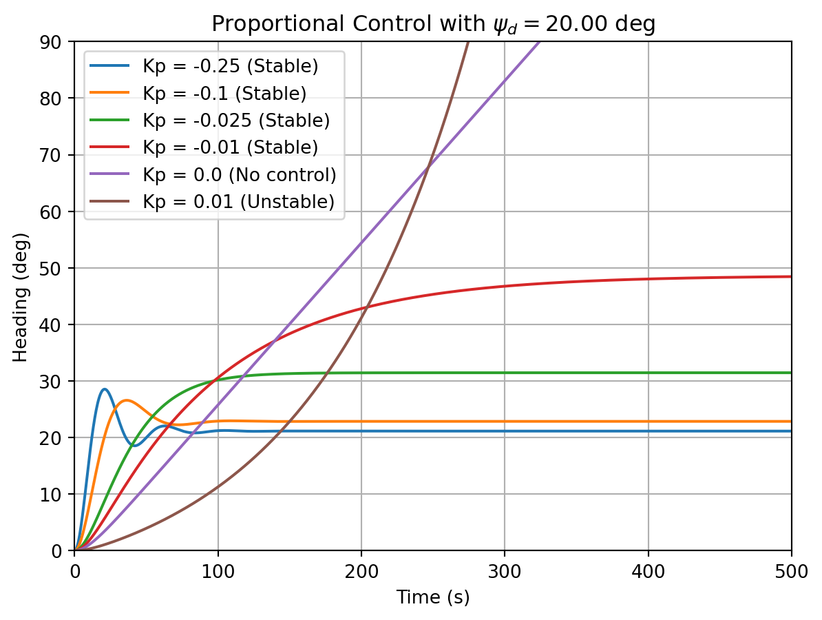
Figure 12.2 shows the response of the ship to a step disturbance with different proportional gains. The ship is initially at a heading of \(0^{\circ}\) and the desired heading is \(20^{\circ}\). The ship is subjected to a step disturbance of \(0.005\) rad/s. The dynamics of the ship are given by a Nomoto model with a time constant \(T = 10\) s and a gain \(K = -1\) /s.
For \(K_p < \frac{1}{4 T K} = -0.025\), the system is stable and has oscillatory response. For \(-0.025 < K_p < 0.0\), the system is still stable and has real poles in the left half plane. Thus the response is non-oscillatory. For \(K_p = 0\), the system has one pole at the origin and is marginally stable. For \(K_p > 0\), the system has one pole in the right half plane and is unstable. As \(K_p\) becomes more negative, the system’s response becomes more oscillatory.
12.2 Proportional-Derivative Control
The PD controller is given by:
\[\begin{align} \delta = K_p (\psi_d - \psi) + K_d (\dot{\psi}_d - \dot{\psi}) \label{eq-pd-control-1} \end{align}\]
Notice that in addition to the proportional term, the PD controller also has a derivative term. The derivative term is used to anticipate the error and take action before the error becomes too large. Substituting \(\eqref{eq-pd-control-1}\) into \(\eqref{eq-ship-dynamics}\), we get
\[\begin{align} T\ddot{\psi} + (1 + K K_d) \dot{\psi} + K K_p \psi = K K_p \psi_d + K K_d \dot{\psi}_d + d(t) \label{eq-pd-control-2} \end{align}\]
A heading autopilot is ususally tasked with maintaining a constant heading in the presence of disturbances. Thus the desired heading is constant and the derivative of the desired heading is zero. Thus \(\eqref{eq-pd-control-2}\) reduces to
\[\begin{align} T\ddot{\psi} + (1 + K K_d) \dot{\psi} + K K_p \psi = K K_p \psi_d + d(t) \label{eq-pd-control-3} \end{align}\]
Taking the Laplace transform of \(\eqref{eq-pd-control-3}\), we get
\[\begin{align} (T s^2 + (1 + K K_d) s + K K_p) \Psi(s) = K K_p \Psi_d(s) + D(s) \label{eq-pd-control-4} \end{align}\]
Thus the steady state output \(\Psi(s)\) is given by
\[\begin{align} \Psi(s) = \frac{K K_p \Psi_d(s)}{T s^2 + (1 + K K_d) s + K K_p} + \frac{D(s)}{T s^2 + (1 + K K_d) s + K K_p} \label{eq-pd-control-5} \end{align}\]
When there is no disturbance, \(D(s) = 0\) and the transfer function of the closed loop system shown in Figure 12.1 is given by
\[\begin{align} \frac{\Psi(s)}{\Psi_d(s)} = \frac{K K_p}{T s^2 + (1 + K K_d) s + K K_p} \label{eq-pd-control-6} \end{align}\]
The poles of the closed loop system are given by the roots of the denominator of \(\eqref{eq-pd-control-6}\) and are given by
\[\begin{align} s = \frac{-(1 + K K_d) \pm \sqrt{(1 + K K_d)^2 - 4 T K K_p}}{2 T} \label{eq-pd-control-7} \end{align}\]
Considering the case with disturbance, the error is given by
\[\begin{align} E(s) &= \Psi_d(s) - \Psi(s) \\ &= \frac{Ts^2 + (1 + K K_d) s}{T s^2 + (1 + K K_d) s + K K_p} - \frac{D(s)}{T s^2 + (1 + K K_d) s + K K_p} \label{eq-pd-control-8} \end{align}\]
For a step input \(\Psi_d(s) = \frac{\Psi_{d0}}{s}\) and a step disturbance \(D(s) = \frac{D_0}{s}\), the steady state error is given by
\[\begin{align} e_{ss} &= \lim_{s \to 0} \frac{Ts^2 + (1 + K K_d) s}{T s^2 + (1 + K K_d) s + K K_p} \Psi_{d0} - \lim_{s \to 0} \frac{D_0}{T s^2 + (1 + K K_d) s + K K_p} \\ &= -\frac{D_0}{K K_p} \label{eq-pd-control-9} \end{align}\]
This is the same value as obtained for the proportional controller. Thus the PD controller does not reduce the steady state error. However, the PD controller has a faster response to the disturbance.

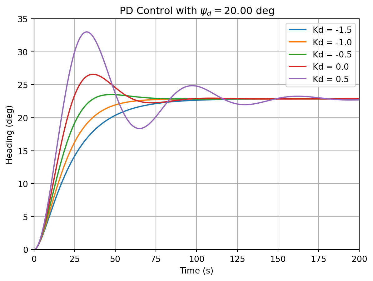
Figure 12.3 shows the response of the ship to a step disturbance with different derivative gains. The ship is initially at a heading of \(0^{\circ}\) and the desired heading is \(20^{\circ}\). The ship is subjected to a step disturbance of \(0.005\) rad/s. The dynamics of the ship are given by a Nomoto model with a time constant \(T = 10\) s and a gain \(K = -1\) /s.
For \(K_d > \frac{-1}{K} = 1\), the system is unstable. For \(K_d < \frac{-1}{K} = 1\), the system is stable. The system exhibits undamped oscillations for \(K_d = \frac{-1}{K} = 1\). For \(K_d < 0\), the system exhibits faster response than the proportional controller (\(K_d = 0.0\)). For \(K_d = \frac{\sqrt{4KK_pT} - 1}{K} = -1\), the system exhibits critical damping and hence the fastest response without oscillations. For \(K_d < -1\) the system is overdamped.